Null 2 Build Guide


The files include additional parts for the buttons so that you can make a spare set if something goes wrong.
There are 3 versions of both switches. They vary in thickness (by 0.5mm) as it's impossible for me to know the tolerances of your laser cutter. Use the one that fits best and moves freely in its corresponding slot.
Tips:
-
Take your time with everything.
-
Read a little ahead in the guide or read the entire thing first.
-
If you get solvent on an acrylic part that it shouldn't be on or in the wrong place. DO NOT touch it, you will only make it worse, simply let it evaporate.
-
Laser cutting plastic leaves it with a slight taper along the edges. It will be obvious which side is the top (the one that doesn’t have the sharper edge).
Using Solvent:
-
Solvent should only be used in a well ventilated area, the fumes can be quite significant. Refer to the guidance and instructions provided on the container.
-
You apply it to the edges of where the materials meet using a syringe or squeeze bottle with a needle, you will see it get ‘sucked’ underneath the acrylic.
-
It’s normal for there to be bubbles between the layers, you will get fewer bubbles if you use more solvent when first applying it.
-
The surfaces being stuck should be clean and free of dust, especially since you‘ll be able to see everything through the clear acrylic.
-
Once the solvent has been applied, it can take up to 3 hours for it to dry fully, but some are workable within 10 minutes. It’s best to just wait.
-
Try not to move the parts as this will create streaks within the plastic that can’t be removed.
-
Do not touch the solvent once it is applied, not even to wipe some excess away, as it will leave a mark.
-
You should receive pieces of scrap acrylic with your case where the holes have been cut out, they are great for practicing with the solvent before starting on the actual parts.
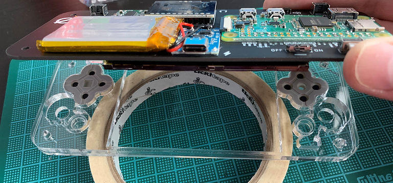
Here's what you'll need (tape, solvent, and something to apply it carefully with), I also recommend some tissue or kitchen roll to wipe down the needle and stop any drips:

Start with the buttons as you have 2 of all the buttons so it doesn't matter as much if you get something wrong.
You're going to be putting the 5mm parts on top of the 3mm parts and applying solvent to the edges marked in blue:

Here's a video showing how to use solvent: https://youtu.be/3KzZDi-aXD4?t=132
For the face buttons, line up the 5mm part with the outline engraved in the 3mm part, wrap a loop of tape around to hold it in place, and apply solvent to the edge (you'll see it get sucked underneath). If you are using the rubber membranes and didn't buy and solder on the optional tactile buttons, you will need to sand down 4 of the 6 round buttons once the solvent has set (explained below).

Here's an idea of how much material you will need to remove from the 3mm end:

You can place the buttons in the front plates with the rubber membrane to check that the button moves freely and isn't forcing the rubber down when not pressed. If you have removed the protective covers from the plates, be very careful not to get sanding dust caught between them as you will likely scratch them if you do.
It's hard to photograph, but the top button has been sanded enough and will travel properly when pressed. The lower button has not been sanded and does not move at all when pressed:


The process is the same for the dpad. Align the 5mm part on top of the 3mm part, tape them in place, apply solvent to the edges where the 2 parts meet, and sand down the bottom if not using the tactile buttons:

Before and after sanding:

That's the buttons done. You should now have a dpad and 4 face buttons that move properly when pressed, and 2 buttons for Start and Select. You can use a finer sandpaper grit if you don't like the slightly frosted look, it's not too noticeable anyway since the buttons are placed over the grey rubber membranes when finished.

Now the back of the case.
Place the 5mm rear inner parts on the 3mm rear plate and tape them in place. Take your time getting this right as your buttons and switches won't work as well if your alignment is bad. The engraved logo goes on the outside.

Double check that you are sticking these parts on the right way around. Place your finished PCB into it to confirm. If you get this wrong, you'll need to order a completely new set of parts so it's worth being absolutely sure.

Apply solvent to the edges marked in blue. The more solvent you use, the fewer bubbles you should get.
Remember: if the solvent drips onto a part that it shouldn't be on, just leave it alone and let it evaporate.
Leave it to dry and all that's left is the assembly! You DO NOT need to stick the front plates together.
Here's an exploded diagram showing how this will all fit together:

First, make sure the SD card isn’t in the Pi and take off your screen protector (with the SD card removed, you are free to
test that the power switch slides back and forth freely). Clean every surface and remove as much dust etc. as you can.
Place the Front outer plate face down (the sharper edges will be facing up) then put the finished face buttons into their respective holes, place the inner front plate on as well:

Place the rubber membranes into the spaces above the buttons and lower the finished PCB into place:
Now the back half.
Place the shoulder buttons, switches, and lower button into their respective places and slide both switches to the right.


Set the switches on the PCB to OFF and muted. Align the top edge of the PCB with the case and close it up like a book:

Make sure all the buttons and switches move the way they're supposed to.
Put the 4 bolts into the corresponding holes and screw the nuts down so that they sit inside the hexagonal holes.
DO NOT over-tighten the nuts and bolts.

Snip off the extra bits of the bolts with a pair of flush cutters.
Be careful: you don’t want to scratch the case and the bolt threads have a habit of firing across the room or into your face.

Check that everything still clicks and slides the way it’s supposed to. If a shoulder button is sticking, try loosening the nearby nut and bolt.
Insert your SD card and you’ve finished the build!
